

 |
| The new NodeMCU V1.0 Dev Kit module Image Source: https://github.com/nodemcu/nodemcu-devkit-v1.0 |
The first “instalment” of the NodeMCU Dev Kit I reviewed had the version number 0.9. It was the first of its kind, since it came with an integrated USB-to-Serial converter and was fitting into a standard bread board. But both key features that would justify the higher price were tainted: at least on Mac OS X the USB-To-Serial converter did not really work well together with the standard tools, especially for firmware flashing.
While it was OK to flash it first with an external converter and then only use it to transfer files to the LUA firmware it was still a disappointment to me. The second problems was the size: it would cover all pins on both sides of the gap on a standard breadboard. This made it hard to connect it to other components. You could still use female connectors and leave the breadboard out in the first place but still, it was a design issue.
Size
It seems that the NodeMCU team learned a lot from the first version and also listened to the community feedback. The second instalment has the version number 1.0 and this truly reflects the maturity of the board. The size of the module has shrunk considerably, making it fit wonderfully in a breadboard: with a length of 48.5mm and a width of 25.6mm it fits also better in casings than the old version (47.1×30.6mm).
ESP8266 ESP-12E Module Riding Piggy-Back
The V0.9 version used the ESP-12 module which is a pretty common choice. For the new version the group around NodeMCU used the newer ESP-12E which comes 4MB of flash memory. This gives you a lot of space to store code and data. The interface to write to the memory also changed, which gave me some initial troubles until the “standard” tools were updated (read more here). Besides the upgrade in flash memory there seem to be more pins available. But I’m not sure to if and how these additional pins can be used. It looks to me as if the same amount of GPIO pins are available (see section below).
Serial-To-USB converter
com_silabs_driver_CP210xVCPDriver(.)::setPowerState - Waking up
com_silabs_driver_CP210xVCPDriver(.)::GetCP210xInfo - Part Number Found: 0x02
com_silabs_driver_CP210xVCPDriver(.)::GetCP210xInfo - UsbConfigurationDescriptor -
com_silabs_driver_CP210xVCPDriver(.)::GetCP210xInfo     .bLength = 9
com_silabs_driver_CP210xVCPDriver(.)::GetCP210xInfo     .bDescriptorType = 0x02
com_silabs_driver_CP210xVCPDriver(.)::GetCP210xInfo     .wTotalLength = 32
com_silabs_driver_CP210xVCPDriver(.)::GetCP210xInfo     .bNumInterfaces = 1
com_silabs_driver_CP210xVCPDriver(.)::GetCP210xInfo     .bConfigurationValue = 1
com_silabs_driver_CP210xVCPDriver(.)::GetCP210xInfo     .iConfiguration = 0
com_silabs_driver_CP210xVCPDriver(.)::GetCP210xInfo     .bmAttributes = 0x80
com_silabs_driver_CP210xVCPDriver(.)::GetCP210xInfo     .MaxPower = 50
com_silabs_driver_CP210xVCPDriver(.)::start - Sucessfully loaded the driver
A nice feature that I didn’t know/have before is that I don’t have to press the buttons or change jumpers anymore before flashing new firmware to the module. Together with the Arduino IDE this happens automagically. This saves you a lot of handwork when writing your code.
The Module Pin-Out
 |
| The NodeMCU V1.0 pin out map. Source: https://github.com/nodemcu/nodemcu-devkit-v1.0 |
Applications
 |
| 3D printed case for NodeMCU, running my code (on the right side) |
 |
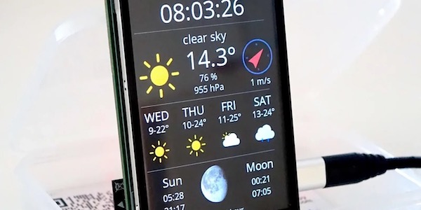
| Multi display output, driven by a NodeMCU V1.0 |
Hi, very nice explanation, Thanks.
I have one question and I can not find an answer on the internet:
Am I able to use NodeMCU Dev Kit V1.0 with UART to another microcontroller? or the RX/TX are blocked by USB-to-Serial connection ?
I would like to be able to send/receive some information through UART to/from another microcontroler. Do you have some hints on this topic?
Thanks,
Adrian
Hi – useful review!
I do have one question though – you say you rewrote your code for the Arduino IDE instead? Does that code using the Arduino IDE talk connect to an OLED display? I'm trying to do the same thing, but cannot make any OLED display work! I'd be keen to see any sample code which might help me?
Many Thanks
Hi David
Yes, it does. Please have a look at https://github.com/squix78/esp8266-projects/tree/master/arduino-ide
There are a few projects that use (and contain) my attempt of a OLED I2C library for the Arduino IDE. Especially look at the weather-station-v2 subfolder, since this is the rewrite for the Arduino platform
Hi Dani,
I've been reading through your blogs over the past few day and I think they're a fantastic resource – thanks for sharing your experiences with us.
I've started playing with the nodemcu unit lately – do you use the actual unit in your projects, or just use it for prototyping, and then switch to a standard ESP device like the ESP-12 for the final version?
Hi Karl
Thank you for your kind words. Its nice to see that my documentation helps other people. That is the best motivation to keep writing;-). About the prototyping question: up until now I have been more of a researcher than applicator. So out of convenience I'm mostly using the NodeMCU module even if running it for a long time. The problem for me with the ESP-12 for me is there incompatibility with the standard hole grid. And since I wouldn't call my self a great solderer I would go the easy way and take an ESP-201 since they have almost the same price but are easily mountable on a prototyping PCB
Hi, Your blog is a good source of knowledge imho. Just fix links in the text 😉
Regards!
Thank you, Bartłomiej. I hope I fixed all of them in this post now!
What is the difference betweeen ESP 0.1V and ESP 0.9V?