

The ESP8266 took the hearts of the IoT and Do-It-Yourself community by storm, due the very attractive price, its internet connectivity and due to the relatively rich amount of available GPIO pins. But an internet connected device is not worth much without means to interact with the real world. Thanks to standardised communication protocols like I2C, SPI and serial interface and the work of the Arduino community there are many sensors and actors available for a really good price. But do they play well with the ESP8266? In this series of blog posts I will share my experience with these modules and how you can use them.
The start makes an input device which is surprisingly low tech but offers a nice way to adjust settings on a display without using too much of your valuable GPIO pins: the KY-040 rotary encoder

What is a Rotary Encoder?
At first glance you might mistake the KY-040 for an adjustable resistor, a potentiometer. It has a knob which you can turn. But unlike real potentiometers the KY-040 can turn round and round without ever getting to a blocking limit. When turning the KY-04 you will also feel certain positions where the encoder will slide into. A potentiometer on the other hand can usually be turned smoothly until you get to the end stop. And there is another difference: the KY-040 (like most rotary encoders) has a switch which can be closed when pressing the knob vertically to the rotation axis. I have seen rotary encoders like this being used in modern radios or in built-in car navigation systems. The advantage is that they can be used relatively easy in a digital system as opposed to an analog/digital converter (ADC) reading the values from a potentiometer. There you also might have to deal with temperature drift and similar ugly problems. So in many ways a rotary encoder is the younger (millennial/digital) brother of a potentiometer.
How do you use a Rotary Encoder?
There are different types of rotary encoders. Some can determine the absolute position/angle of the knob without constantly keeping track of its movements. But the KY-040 a very simple minded fellow. By tracking the signals on two pins an MCU can determine if the knob was turned to the left or to the right. With a third pin the state of the knob button can be tracked. The wave form on the two rotation pins looks more or less like this:

Lets get our hands dirty!
Now to a practical example. Wire up your encoder like this the following picture, make sure that you follow the labels and not the ordering, I might have turned something upside down:

- GND to GND
- + to 3.3V
- SW to D3
- DT to D2
- CLK to D1
Installing the library
There are different libraries that might work. This library worked well for me: https://github.com/PaulStoffregen/Encoder Download the ZIP and unpack it into your Arduino library directory. Restart the Arduino IDE and copy the code from here:
#include <Encoder.h>
Encoder myEnc(D1, D2);
long oldPosition = -999;
boolean isButtonPressed = false;
long lastUpdateMillis = 0;
void handleKey() {
isButtonPressed = true;
}
void setup() {
Serial.begin(115200);
Serial.println("Basic Encoder Test:");
pinMode(D3, INPUT_PULLUP);
attachInterrupt(D3, handleKey, RISING);
}
void loop() {
long newPosition = myEnc.read();
if (newPosition != oldPosition) {
oldPosition = newPosition;
Serial.println(newPosition);
}
// software debounce
if (isButtonPressed && millis() - lastUpdateMillis > 50) {
isButtonPressed = false;
lastUpdateMillis = millis();
// Reset the counter
myEnc.write(0);
}
}
After uploading the sketch you can open the serial console, turn the knob up and down and press the axis to reset the counter. Your output might look something like this:
Basic Encoder Test:
0
1
2
3
2
3
4
0 - Knob pressed
1
2
3
4
0 - Knob pressed
Suggested applications
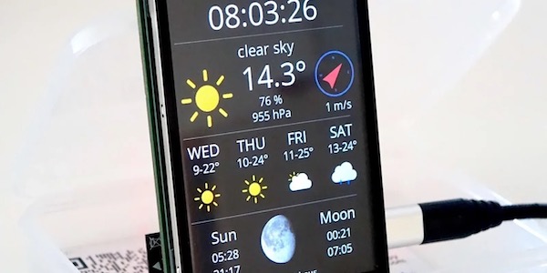
- WeatherStation Frame Controller: Some readers were asking me how they could control the currently displayed frame of the WeatherStation. Depending on the amount of the frames you are using it might take a while until the one that interests you the most comes around. The rotary encoder is a nice extension which allows you to quickly zap through the frames without having to implement a lot of code
- Wifi Selector for unprotected APs: lets assume you have a setup with an ESP8266, a display and you want to quickly select an unprotected wifi to connect to without using the web interface: just implement some kind of menu and use the rotary encoder to move a cursor from one SSID to the next and the knob button to select the AP you actually want to connect to
Where to buy?
As always I recommend to order it from my favourite Chinese retailer Banggood
Hi.
Is it formatting error in code?
————————–
if (isButtonPressed && millis() – lastUpdateMillis > 50) {
————————–
wrong letters?: && and >
Hi Frank. Depends what exactly you see. It shoulb be two ampersands and one “greater than” sign…
Don´t you have problem compiling in Arduino IDE ? I put the board esp8266 generic or Wemos D1 mini and i get errors with library. Pin definitions errors compiling
Hi Raul
No, I don’t have any problems. Did they get resolved in the meantime?
Daniel
I’m getting 4 counts per click, both + and _- direction.
Using Paul Stoffregen / Encoder library.
I have checked other libraries and cannot resolve the issue with the ESP8266.