

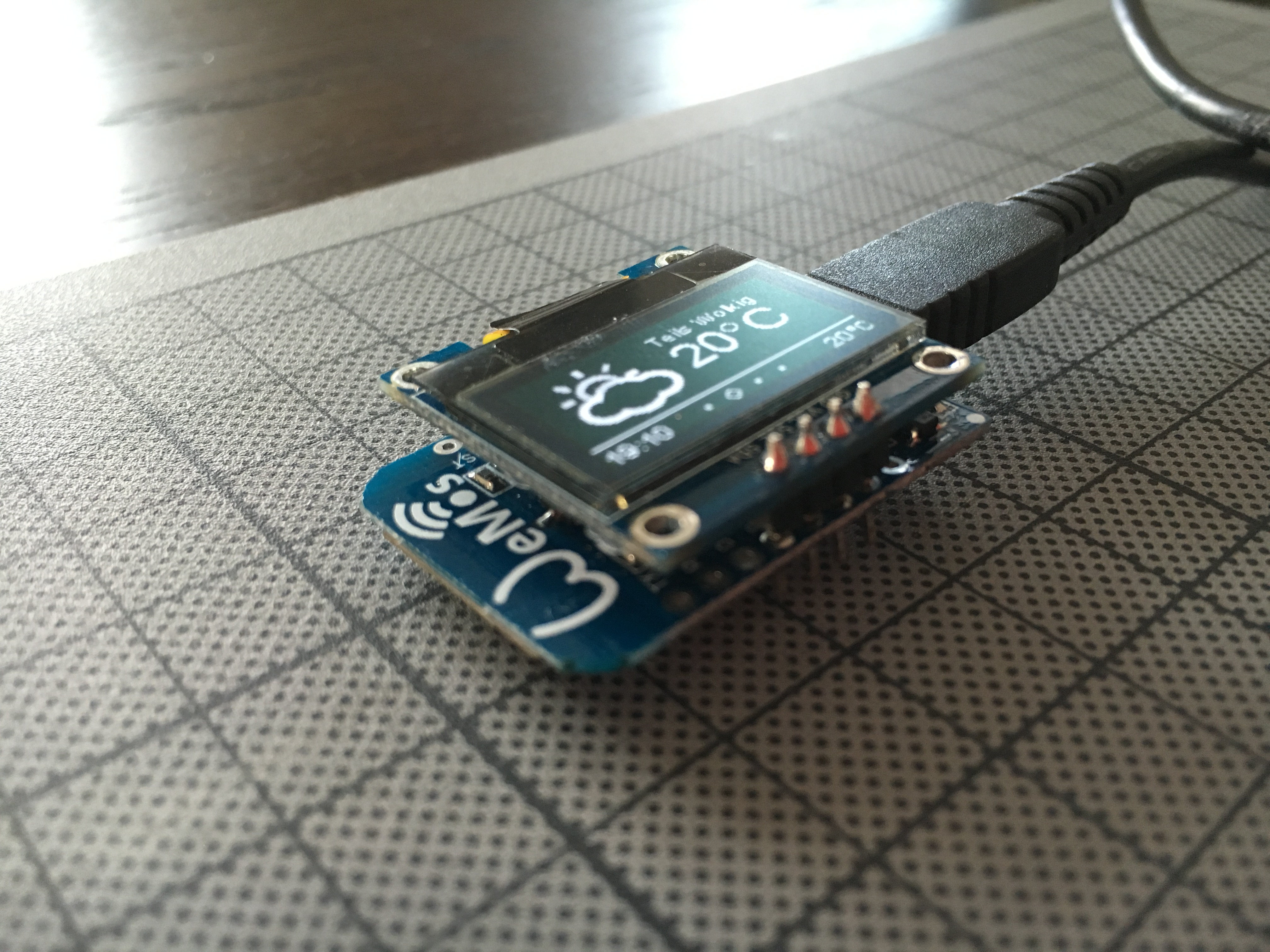
Inspired by Mike Rankin’s (@mikerankin) beautiful crossovers between an ESP8266 ESP-01 and an 0.96 Inch OLED I2C display I decided to try if there wasn’t an easy hack to marry the two components with as little soldering as possible.
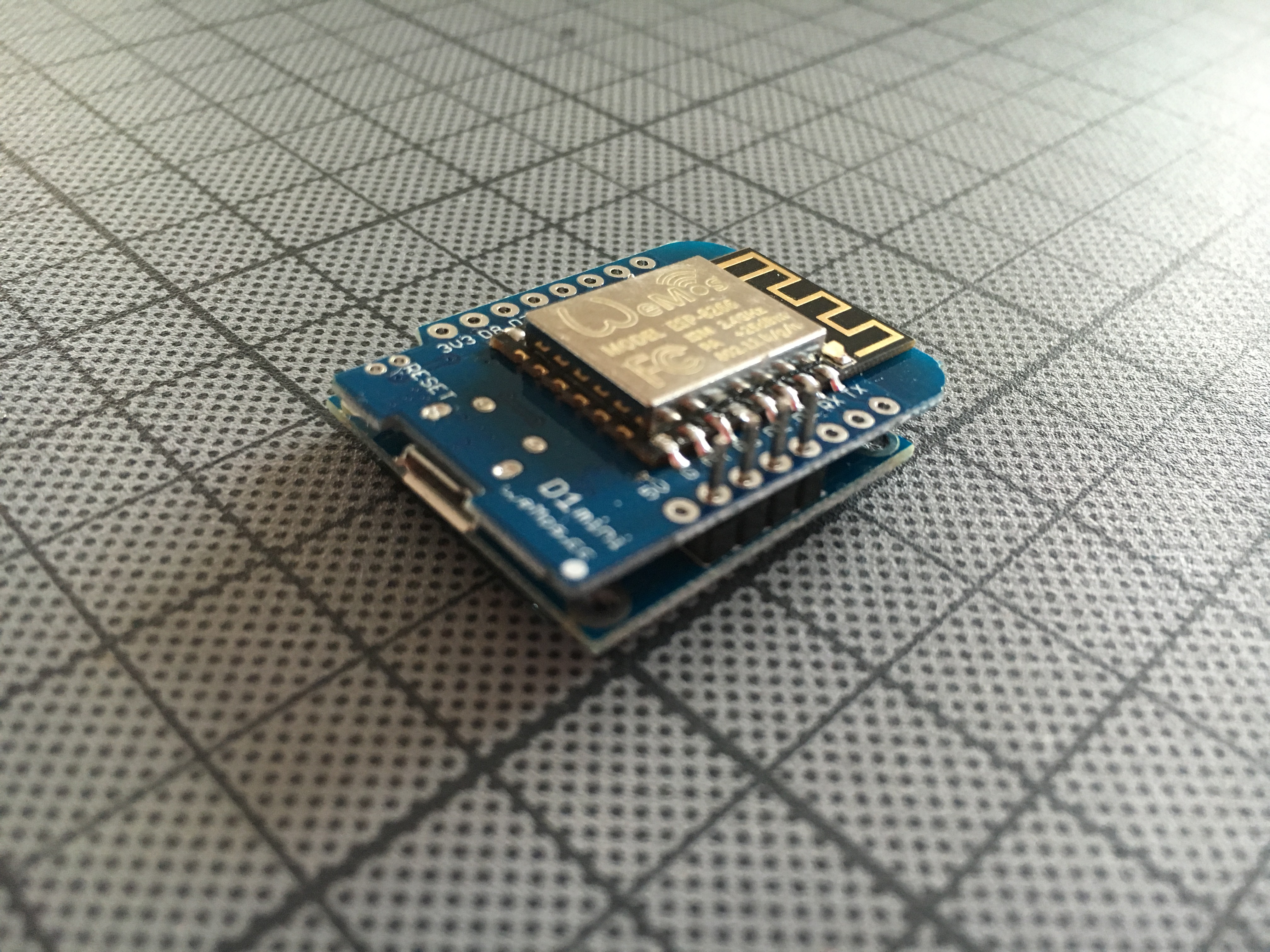
After turning, connecting and flashing different combinations of the two modules I finally found one that only requires you to solder 4 connections. Assuming that your display’s connectors are in the order GND, VCC, SCL and SDA just place the display on the bottom of your WeMos D1 Mini so that the two GND’s are connected with each other. VCC connects to D4, SCL to D3 and SDA to D2. I’m aware that I am “cheating” the D4 connector into being the power source, but I couldn’t find any data about the max. current the display draws. If you want to be 100% save add a connection between VCC (on the display) and 3V3 instead. Let me know in the comments if you are convinced that I’m doing something reckless.
If you are following my VCC-D4 hack from above make sure that you enable D4 for output and to set it to HIGH:
pinMode(D4, OUTPUT);
digitalWrite(D4, HIGH);
Resources
Shopping List
- WeatherStation Kit for Soldering (you are supporting my blog)
- SSD1306 0.96 Inch Oled Display (from Banggood)
- WeMos D1 Mini (from Banggood)
Hi,
Used the same Wemos + Oled setup before, see here:
http://forum.wemos.cc/topic/112/alternative-for-d1-mini-oled-shield
Have a look at the comment there, the power from an IO pin seems to be limited to 12 mA.
Hi Gerard
Thank you very much for pointing this out! Do you think connecting 3V3 with D4 and setting D4 to input mode with a PULLUP could resolve the problem? That would still allow for easy soldering…
Cheers,
Dani
Hey, thanks for this tip, and you know what, I’m buying these I2C Oled for years see https://github.com/hallard and guess what new OLED version have VCC/GND reversed, It’s a pity since I got all by boards with old pinout
VCC/GND/SCL/SDA but the good new is that if you buy a “old” oled you can plug it as is with VCC to 5V GND to GND and then SCL=GPIO2 and SDA=GPIO0
Could works but need to be tried since GPIO2/GPIO0 need special level to but ESP8266
You can find old one here
http://stores.ebay.com/G-C-Supermarket-HK-Co-Ltd/_i.html?_nkw=IIC+128×64+oled&submit=Search&_sid=1090683909
Re. supplying power to the OLED from a digital pin:
In an OLED, each pixel is an LED so the current consumption is directly proportional to how many pixels are on, for the display you have the current consumption will be ~0mA with all pixels off and ~30mA with them all on bright.
The official spec limit for a digital pin is that it can supply 12mA, this is while still meeting the logic 1 level. In practice the pins can deliver more, but the voltage at the pin will sag and thus the display will get dimmer as more pixels are turned on. For text based displays the consumption will probably stay below 12mA.
Typical devices allow a short circuit indefinitely on any one output pin so it is unlikely the ESP8266 will get damaged from powering a small OLED, Communication may however become unreliable if the pin voltage sags too much under load.
Using a digital pin to supply power is one simple way of turning on/off the display when entering power down mode to save power.