

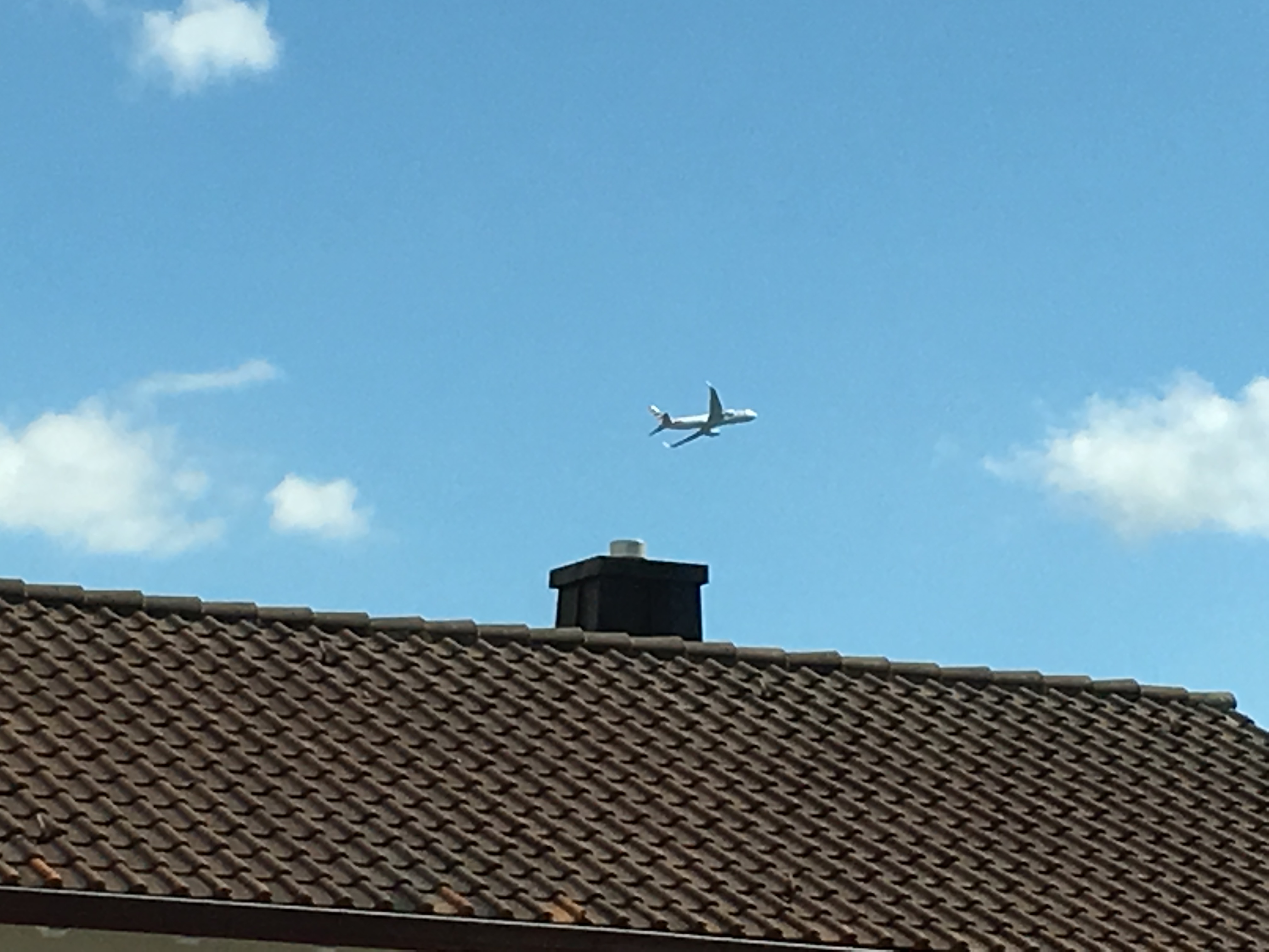
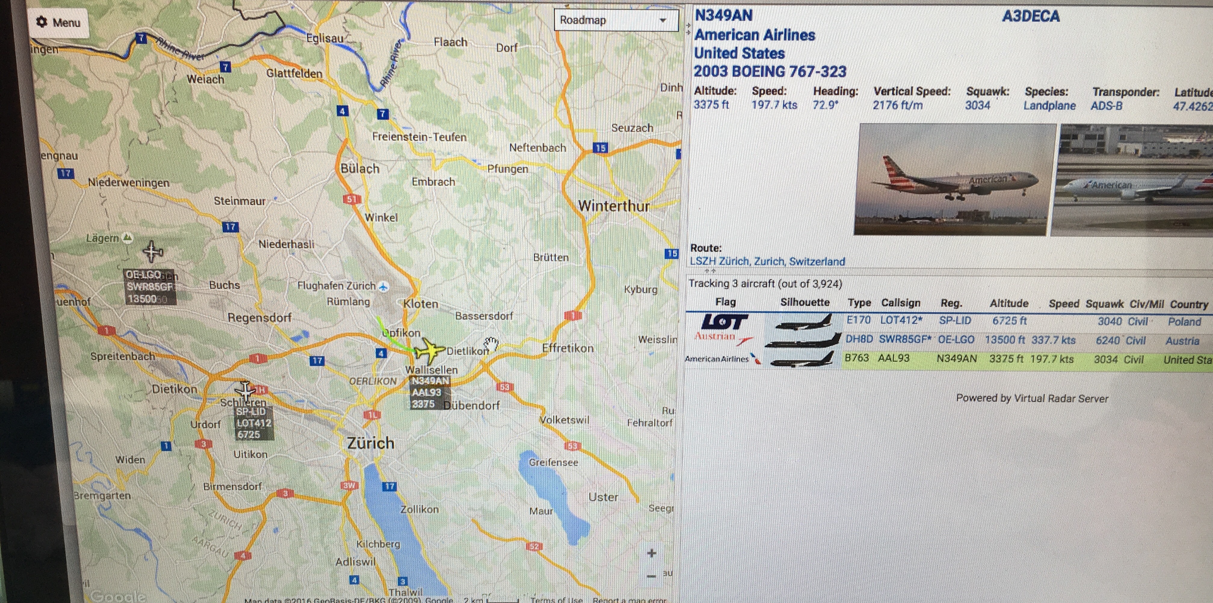
When I sit at my living room table I can see wonderful big airplanes in the final approach to Zurich (ZRH) airport or ascending to a far destination: Airbus A380 or Boeing B777 are ingenious proof of what we are capable to design and build. Quite often when I have visitors I start flightradar24 to get more information about the airplanes we see. But wouldn’t it be nice if this information would just be there, anytime I’m curious – without starting an app on my smart phone? Since I’m playing a lot with the ESP8266 it was an obvious choice to build such a device by myself. I actually had already built one a while back with the Flight-O-Matic but the setup was quite complicated and the project was dormant for a while. Until I recently discovered a service that provides exactly the information I needed and is free to use as well.

What you’ll need
In order to get this project running you’ll need the following list of hardware:
 | NodeMCU ESP8266 module or Wemos D1 Mini |
 | 0.96" SSD1306 OLED display |
 | A few connectors and USB Wire |
 | Or order a complete starter kit for USD $19.90 (incl. shipping) from my shop and support this blog.
|
Depending on the coverage of adsbexchange.com feeders in your area you might also buy the following items:
- Raspberry Pi (Model 3 recommended but also works with older versions and probably Zero)
- RTL-SDR dongle for receiving the ADS-B signal
- Micro SD card for Raspberry Pi (for Model 3 or with adapter, depending on your RasPi model)
The Service – ADSBExchange
At the core of this project is the excellent service provided by Dan Streufert and countless people feeding live transponder signals into it: http://adsbexchange.com. From what I understand it is built on top of the http://www.virtualradarserver.co.uk/ project and lets you query live position data based on location, distance to a point, altitude etc and returns a JSON object which you can process in your code. Please note: in order to keep this service free-to-use Dan depends on your support, either by donating money to cover the server hosting costs or by providing your local data to improve coverage.
Note, this step is optional: When I first checked the coverage of the Zurich airport wasn’t so great so I decided to reactivate my RTL-SDR DVB-T dongle (see posts here, here and here) and contribute live data to adsbexchange.com. If the coverage in your area is insufficient consider to setup such a feeder as well.
Once you have the hardware (see above, Raspberry Pi and RTL-SDR dongle) you can either do the setup manually or take a short cut by becoming a flightaware feeder and using their ready-to-feed sd-card image called PiAware: http://flightaware.com/adsb/piaware/install. Once you have done that you have to setup your PiAware instance to also feed to adsbexchange.com by running a script provided by Dan: http://www.adsbexchange.com/how-to-feed/
The Plane Spotter Hardware
Once you are sure you have a good coverage of your area of interest you can start to get to the actual plane spotter hardware. I recommend to either use the components provided by my IoT Starter Kit or to get the setup I described in this post using the Wemos D1 Mini which requires soldering but yields a very compact setup. The wiring is described here.
The Code
UPDATE: this section describes the Platformio IDE project setup. In the meantime I have made it available also as example project in the WeatherStation library. Read more about it here if you prefer the Arduino IDE.
In my recent ESP8266 projects I started switching to the PlatformIO IDE since it is a lot more convenient to use compared to the Arduino IDE: automatic library dependency management, better coding support in the editor and great Travis CI and even Continuous Delivery support. So please make sure that you have a running IDE before you get started with the code. Once you have that ready please checkout the code from my github repository.
Now the most important part is to configure the QUERY_STRING variable in the main.cpp file:
const String QUERY_STRING = “lat=47.424341887&lng=8.568778038&fDstL=0&fDstU=10&fAltL=0&fAltL=1500&fAltU=10000”;
For a detailed description please checkout the documentation of the virtual radar server. What my example does is to filter out all aircrafts which are not within 10km from a location south of the runway and above 1500 feet (I don’t care about landed airplanes) or above 10000 feet (I also don’t care about transit airplanes). There are many options to adapt this query to your needs, so please carefully read the afore mentioned documentation. Once you are ready with the query you can flash the firmware on your ESP8266 chip.

First Run & Adapting it
Since the ESP8266 is fetching the data from the internet you’ll have to connect the module to the internet. My code is using the excellent WifiManager library. If your ESP8266 cannot connect to a (known) access point it will start an AP by itself and allow you to connect through your Wifi settings to it. A captive portal window opens and lets you select the correct SSID and enter the password. It then stores the Wifi settings on flash and will use it in the future.
If everything works you can go on and change the way the data is displayed or extract more data from the adsbexchange json object. It would be great if you could share your results with me either here in the comments or on Twitter. I’ll be happy to share it with the community.
Summary
You can build a cute little plane spotting tool with just a few components for under $20 without much work. If the coverage of your area on adsbexchange is poor then you could become a data feeder for about $50.- more (Raspberry Pi + RTL-SDR Dongle). Playing with the real-time data is fun and can be a very rewarding weekend project!
Great project! Have all components and already suceeded ploting data from sdr but esp+oled always feel magical 😉
One question, you have mentioned wemos d1 mini, what driver are you using? my existing doesnt work with it although it uses ch340g (it works with witty)?
Great project, I made a small copy under Arduino IDE as I have problems starting up with platform IO. now adding the displayfunctions… I also ordered a magnetometer, my final idea is to point the device in the direction of a plane that I can see and that the display shows me the info on that plane. Do you think that is feasible?
Hi Hans. I guess the magnetometer would be a very cool addition to the orginal project and should be very much feasible. Maybe even add a GPS module into the mix and you won’t have to hard code the current coordinates. You mentioned that you had some issues with platformio. I heard that from several people but never really in details. Can you tell me a bit about the problems you ran into? I might write a clearing article about it then…
– Daniel
Hans, any chance you could gift me a copy of your Arduino IDE code for this project as I can’t get it working with PlatformIO either?
PlatformIO always says that it can’t find port COM 9. I’ve tried modifying the platformio.ini file and this makes no difference.
Hi Stephen. If I’m not mistaken just rename the main.cpp into Plainspotter.ino and move everything into a folder called Plainspotter. Now Download all libraries using the library manager (the platformio.ini contains a line defining all libraries) and you should be good to go. @Hans, please correct me if you had to do more than that… About the com port: which OS are you using? Is the Arduino Ide seeing the port? Maybe an issue with drivers or r/w permissions?
Hi Daniel, everything builds successfully, but when I try to upload to the module I always get his error message.
espcomm_upload_mem
error: Failed to open COM9
error: espcomm_open failed
error: espcomm_upload_mem failed
scons: *** [upload] Error -1
[ ERROR ] Took 34.57 seconds
I’m using Win10 Pro 64 bit and the ESP8266 is on COM4. The Arduino IDE program finds and uses the COM port with no issue, but PlatformIO always gives me the above error message.
So I can use the WeatherStation program with no issues because it is an Arduino IDE project, but I can’t use PlaneSpotter because it needs PlatformIO, and PlatformIO is a problem for me.
Hi Daniel
Just an update for you.
I got to the bottom of why I constantly got the error message I got in my previous post. My internet security program was treating PlatformIO as malicious software and wouldn’t let it send any data.
Using your PlaneSpotterDemo and Arduino IDE 1.6.4, Plane Spotter is now working perfectly on your WeatherStation Kit!
I’m now trying to figure out how to decode more data, in addition to “To/From” and “Aircraft Type”, such as “Operator Code”, and display it too.
Many thanks for a great project!
Stephen, looks like you’ve came across some other problem too;) You see, as you said you got esp on COM4 but look at the info from platformIO: it tries to connect on COM9. It happens when you don’t have upload_port specified in your platform.ini file and use multiple USB ftdi base devices. Just add to platform.ini upload_port=COMx, where x is current port you are using for ESP and you should be all set;)
Best wishes
Hi, cool project! I ordered one of your ‘Weather Station Kits’ so I could build it. Today I got a package but it only contained the MCU, not the display nor the jumpers. Could you email me? Cheers!
Hi Costa
As mentioned in the email to you the following sometimes happens: my supplier splits the order into two or more deliveries to ship parts of it faster. If you chose to pay for additional tracking you can follow each of the separate parcels and track them up to your door steps. Please let me know (here) when everything arrived…
Kind regards,
Daniel
Hi,
I’m new to all this I tried your weather app, so I moved on to this, for the life of me I cant get it to work, when uploaded to the Wemos I just have a blanks display, do you have a version of code that runs for the arduino-1.6.9 version
Regards
Hi Paul
My first suspect would be that you have the pins set wrong. Two suggestions to make sure this is true: do you get results from fetching the data from adsbexchange.com in the serial console? If yes, this means that everything is fine and just the display is not working. In that case I suggest that you first get the display working in the Arduino IDE with the OLED library example (File > Examples > ESP8266 OLED display driver for SSD1306 > SSD1306UiDemo) or from here: https://github.com/squix78/esp8266-oled-ssd1306/tree/master/examples/SSD1306SimpleDemo
Make sure that you have the correct pins attached:
// D3 -> SDA

// D5 -> SCL

SSD1306  display(0x3c, D3, D5);
And there is also a chance that your display or the output pins that you planed to use are broken. Try to use other pins and don’t forget to adapt the code! Please let me know if it helped!
Ok the simple demo works just fine.
the planespotter app wont compile as I get the following error
GCC error ‘D3’ was not declared in this scopeat line 70 col 40
GCC error ‘D4’ was not declared in this scopeat line 70 col 44
GCC error ‘SCL_PIN’ was not declared in this scopeat line 77 col 55
GCC error ‘D3’ was not declared in this scopeat line 70 col 15
any ideas>
Ok just to add now working. I had to change the display code so it now just this
SSD1306 display (0x3c, D3, D4);
OLEDDisplayUi ui( &display );
Hi Daniel,
congratulations for your great project(s)!
I have added a few lines to your code in order to display a message when there are no planes in range. I have added them to the “drawHeaderOverlay” function…
else if (!adsbClient.isAircraftVisible()) {
display->setTextAlignment(TEXT_ALIGN_LEFT);
display->setFont(ArialMT_Plain_16);
display->drawString(10, 10, “No planes”);
}
Is it the right place to add this? Is “drawHeaderOverlay” the right place to interact with other I/O, for example adding a few leds or a neopixels in order to tell me when there are visible planes in range?
Thanks and best regards!
Hi Fernando
Yes, the drawHeaderOverlay function is the right place to display the “No planes” message. Good idea, by the way. You could even add some information like “No airplane seen in the last 5 minutes”…
I wouldn’t add interaction with other hardware into the drawOverlay functions. It would work but it is really bad style, since the drawOverlay function is for drawing to the display. A better place would probably be to add it to the main loop. And if you are worried about smooth animations you probably should make sure that you have enough cycles left in order to do the hardware interaction with this block of the main loop:
int remainingTimeBudget = ui.update();

if (remainingTimeBudget > 0) { ..}
I hope that helps!
Can you be more specific exactly where the extra code is dropped into? I have found the “drawHeaderOverlay” section is but its not compiling once I add it? – Also, it runs fine, but after about 30 minutes or so it just stops with a “stack” error in the serial monitor – any ideas?
If you want to add GPS support I have very good experiences with this cheap gps module: http://www.banggood.com/1-5Hz-VK2828U7G5LF-TTL-Ublox-GPS-Module-With-Antenna-p-965540.html?p=6R31122484684201508S
It has everything on board, and works directly from 3.3V. Has a good reception, acquires gps signals in ~30 seconds cold. When placed close to a window I could get stable reception even indoors.
I used a GPS like that on another project (hackaday.io/project/5180-real-simple-and-cheap-gps-navigation). I might try to combine both systems to show the planepositions on my map…
I also added an offset to the heading arrow in order to have it pointing the direction the screen and i am facing:
#define LOCALHEADING 170 // this is what you measure holding a compass the direction you are facing at
Then i subtract it in the drawHeading call:
drawHeading(display, 78, 52, adsbClient.getHeading()-LOCALHEADING);
In my case it is 170 degrees as this is the orientation of my terrace (170 degrees = almost oriented to the South). This is how I will be looking both at the screen and at the planes.
As the arrow is drawn with trigonometric functions we just subtract the offset without caring about it being negative, right?
Cheers!
Nice project
How difficult would it be to combine this with your weather app on the same hardware?
I’d love to create something like this with a toggle switch to select either weather or plane spotting mode.
Is this feasible?
Hi Jamie. Depending on your programming skills this should be very easy to do. A switch would be one option but you could also consider a rotary encoder, then you can select the modes by turning the knob and pressing the axial button: http://blog.squix.org/2016/05/esp8266-peripherals-ky-040-rotary-encoder.html
You basically just have to implement two sets of drawing functions, one for the plane spotter, the other for the weather station…
Great project !
I have been trying to use it with a Wemos OLED shield (64×48). Unfortunately the library used in your project is specific to the 128×64 pixel OLED display. In other words, the code is running but I can only see a part of the “real display”.
Any idea on how I could use the 64×48 display ?
Thanks in advance.
Hello!
I try this weekend to build my own planespotter (via arduino weather). But so far, I have no luck. I get the error:
PlaneSpotterDemo:79: error: ‘D3’ was not declared in this scope
const int SDA_PIN = D3;
^
PlaneSpotterDemo:80: error: ‘D4’ was not declared in this scope
const int SDC_PIN = D4;
What have I done wrong?
The D3 and D4 pins are only declared if you use an ESP8266 NodeMCU or Wemos board. For other boards you have to replace D3 and D4 with your GPIO pin number… Good luck and let me know if this tip helped!
Thank you! I try tonight hopefully and let you know.
Finally I managed to get it compiled and on the serial console, I can see a lot of traffic going on. Unfortunately, it seems that I have bought a wrong version of the little tv screen. I have much more connections like RES, DC and CS. Silly me!
Now I have to find out how to cable it and wait 4 damn weeks until I get the next version from far east.
This allows it to program and serve files faster,in comparison with being attached
to the department computer serving the applications.
Intelinet Systems, which was providing IT services more than 26 years
to companies in diverse sectors, contains the resources along with the expertise to offer such crucial security services for network backup
software in an attempt to make sure your valuable business records are increasingly being
safely stored. The enterprise information is fed into pricing and risk analysis data warehouse models.
Seems that adsbexchange has changed from http to https for the public-api. To get it work I changed:
// const char host[] = “public-api.adsbexchange.com”;
const char host[] = “global.adsbexchange.com”;
(Still waiting for my display)
Reply to myself, its much better so change to https, and thats easy:
In AdsbExchangeClient:
use WiFiClientSecure client; instead of Wificlient
set the httpsPort to 443 (I defined a new variable)
I haven’t expected that the small esp is able to decrypt ssl-connections.
Oliver thanks for your advice. Unfortunately I still can’t connect to adsbexchange. Would it be possible for you or Daniel to post a step by step guide to reconnecting to adsbexchange, or perhaps to FlightAware? Thanks
Hi,
for connectiing to adsb-exchange you need to edit the AdsbexchangeClient.cpp (I am working in arduino-IDE).
Go to line 11 and change WifiClient to WifiClientSecure
Go to line 18 and edit httPort, change 80 to 443
Upload again to your planespotter and it should work again.
At the moment (06 Nov 2016, 14:10) it seems that there are no data on adsbexchange. Cannot see any plane even on the webpage.
Oliver
Thank you for this, it was very helpful.
As you say, there was no data on adsbexchange for a number of hours. It has just come back to life and I’m now receiving data, it maybe was a server outage?
Seems that they still have problems, receiving is working at the moment, but feeding does not work properly.
adsbexchange now sending data again…..but for how long?
Hello,
Thank you for these projects that are very instruction for a beginner like me.
I started a Piaware and a plane spotter and I would liked to send an http request (http://192.168.1.58/on) when the number of aircraft is greater than or equal to 1 ….
i made several attempts but not being computer scientist, my tests were not conclusive.
Can you give me the syntax for this type of request?
thank you in advance
Hi Gael
I am not quite following. Are you trying to call to your PiAware instance from your ESP8266? And what would be the desired outcome?
Hello,
i want to send a HTTP request between the Wemos Plane Spotter and other wemos with color LED.
i want to change the color of this led when an airplane fly over my house…
i used this project “https://github.com/Miauto/Fi-DEL”
i need to send a request like this when a plane fly over my house :
http://IP_wemos_LED/red
And when he does not have a plane flying over my house :
http://IP_wemos_LED/blue
Thanks et “Bonne nuit”
Squix78 – Tell what bar you like (i.e. best options), ask them if they accept Paypal and let me know their address, I will pay you not only one but a couple of beers! this is what I was looking for and cant afford the time, but I can afford the beers!!
Hi all, since some time there was a little bug in the code with the daylight saving time. My station was not picking that up so during winter the time was off 1 hour and I kept changing UTC_OFFSET every 6 months between 1 for summer and 2 for winter. I found a little workaround. I am posting this here too. Dani had already made some code which can get the time from the local wunderground station so I used this today and it works like a charm!
In the main sketch just locate the function bool drawFrame1() and change here 1 line, the one where string time gets the time assigned:
bool drawFrame1(SSD1306 display, SSD1306UiState state, int x, int y) {
………………………….
//String time = timeClient.getFormattedTime();
String time = wunderground.getHours() + “:” + wunderground.getMinutes() + “:” + wunderground.getSeconds();
………………………….}
@Dani
I do have it correct right? Or is there a reason why you did not use this timesource?
I ha ve a small problem: The displayed text is in the wrong direction.
Do you know why? Could we rotate the text ?
this might help display.flipScreenVertically();
Thank you, that works
Hi and thx for this great thing of iot!
i installed 4 sensors in different locations and different wifi´s and all my nodes a crashing after a few days and dont send data anymore. is there any known issue that can hangup the weather node in this behavior?
thx from Germany Frankfurt
I bought two weather station kit with DHT11, all work good, but I can’t get DHT11 working good, always got NAN information from the module. Im using WeatherStationDemo and esp8266-dht-thingspeak-logger where modify those lines to use DHT11 and D6 pin in MCU
// DHT Settings
#define DHTPIN 6 // what digital pin we’re connected to. If you are not using NodeMCU change D6 to real pin
// Uncomment whatever type you’re using!
#define DHTTYPE DHT11 // DHT 11
//#define DHTTYPE DHT22 // DHT 22 (AM2302), AM2321
//#define DHTTYPE DHT21 // DHT 21 (AM2301)
Always got this
WiFi connected
IP address:
192.168.0.102
connecting to api.thingspeak.com
Requesting URL: /update?api_key=———————–&field1=nan&field2=nan
HTTP/1.1 200 OK
Content-Type: text/html; charset=utf-8
Content-Length: 2
Connection: close
Status: 200 OK
X-Frame-Options: ALLOWALL
Access-Control-Allow-Origin: *
Access-Control-Allow-Methods: GET, POST, PUT, OPTIONS, DELETE, PATCH
Access-Control-Allow-Headers: origin, content-type, X-Requested-With
Access-Control-Max-Age: 1800
ETag: “6364d3f0f495b6ab9dcf8d3b5c6e0b01”
Cache-Control: max-age=0, private, must-revalidate
X-Request-Id: 4539c208-db0e-4f85-ba42-a32d92c8ac38
X-Runtime: 0.049378
X-Powered-By: Phusion Passenger 4.0.57
Date: Mon, 27 Mar 2017 12:56:55 GMT
Server: nginx/1.9.3 + Phusion Passenger 4.0.57
Any idea what i should do to solve this issue.
Thanks in advance
Coffee money was sent! Thanks for all the great code and documentation. Built both the small OLED and Color weather stations. Now just wrapped up a variant of the color version Fowlerk created. Fantastic mods he did to your original.
I’m trying to adapt the weather station demo code so that it will have multiple levels of frames. I think there would be a lot of interest if there was a blog posting showing how to do it. What I hope to achieve is to have one of the main frames show the temperature, and if a selection is made at that time it will then display the set of frames as done in the demo.
A second frame at the top level (after the temperature frame) could display information from a service like Thingspeak. Making a selection at that time would present a new set of frames with more information, like the weather set.
The third frame, etc. …
I live in Wallisellen, I need to do this!
It seems that it doesn’t work anymore.
After the setup of the WIFI, the display remains blank except for wifi gauge
Any idea ?