

In this project I will show you how you can build yourself a fancy Withings-like body scale. I divided the article into two parts: Part 1 describes the hardware hack and Part 2 the software. In this project I used a cheap scale I bought in the local super market for 9 Swiss Francs (which is currently about USD $9.-) and I am optimistic that other digital scales will work for you as well. This project was a lot of fun since I had to do reverse-engineering, soldering, programming and (optionally) even 3D modelling and printing. I hope you will enjoy it as much as did!

Before we begin
Just a little word of warning: you might be taking apart a working digital body scale. I cannot guarantee that your retrofitting will actually work and you might end up having just a broken body scale. Because of this I recommend that you are using a cheap or old digital scale rather than an expensive working one…
The other thing I’d like to mention: it took me many hours of my scarce free time to build and document this project. While I am not depending on income from this blog I still very much appreciate teleported beer (donation), you following one of my affiliate links or buying something from my shop. Thank you!
This is a write up of a project I started about a year ago. The project went back onto my “work-in-progress stack” and was waiting for a revival. Back then I also wrote a quick article about it.
What you will need
The components I used in my project set me back between USD $30-40 including the body scale. The following list should give you an idea what components you’ll need and what you should be looking for.
| Image | Description | Where to buy |
|---|---|---|
 | Digital Body Scale: It is very practical if you can build your smart scale project on an existing digital scale. From what I can tell modern digital scales all use the same kind of sensor (load cell) but I cannot guarantee it | Switzerland: Coop. IKEA also has a low-cost scale: IKEA |
 | The ESP8266 module is the next important component. It is the brain and mouth of your smart scale. I recommend a small development module like the Wemos D1 Mini: it has enough pins and is small | Banggood |
 | The HX711 module is a so called Load Cell Amplifier and will convert the weak analog signal from the weight sensor into bits and bytes the ESP8266 can understand. | Banggood |
 | Power Source - I picked a Lifepo4 AA-type battery since it provides the perfect voltage and has a considerable amount of capacity. The AA packaging (14500) also helps to buy or 3d print a good holder. If you don't own a 3d printer also buy a AA-cell holder | AliExpress |
 | These OLED displays are just wonderful: since the pixels glow by themselves the contrast is very high. You can choose between the 0.96 inch SSD1306 display or the 1.3 inch SH1106 one. The smaller one you can buy in the Squix Shop, the other you'll have to order from AliExpress or similar | 0.96" Oled Display: Banggood 1.3" Oled Display: Banggood |
Besides these “core” components you will also require wires, solder and solder iron, screw drivers.
Understanding the Body Scale
So here is the plan: you open up your pretty body scale, remove everything you don’t need and keep the load cells (the components which measure the weight) in place. Then you connect the load cells to your HX711 amplifier module and connect the amplifier to your ESP8266. Then you’ll need to attach the OLED display to the ESP8266 as well and bring in some kind of power source with an on-off switch. Easy, isn’t it?

For me the hardest part was to figure out how the load cells should be connected to the HX711. Luckily the load cells were attached to a mini PCB which in turn was soldered with only a few pins to the main board of the body scale. So I only had to figure out how to connect the four pins of the mini PCB to the HX711 module rather than figuring out how to connect the 12 wires of the load cells (3 wires and 4 load cells). I don’t know how your scale will look like. Maybe you will be lucky as well but it also could be that you have to do some hard core reverse engineering. Maybe the following pictures will help.

I suggest that you test the setup on a bread board before you take out the soldering iron. This way you can easily switch the wires until everything works. SparkFun has a very good introduction to load cells and the HX711: Sparkfun Load Cell Tutorial
Connecting the load cells and the HX711 Amp
Now that we (hopefully) have figured out how to use the existing load cells we have to connect them to the amplifier and the amplifier to the ESP8266.

Again, how you connect the load cells to the HX711 requires a bit of educated guessing. Read through the previous chapter, read the SparkFun tutorial about load cells, use the color codes of the wires. Then connect the HX711 to the ESP8266. The following image is just a zoomed in version of the complete wiring below:

Connecting the OLED display
If you are familiar with my WeatherStation project or the ESP8266 based plane spotter then the wiring of the OLED display should be straight forward. Just connect VCC on the display with 3V3 on the ESP8266, GND with GND, SDA on the display with D6 on the ESP and SCL with D7. In theory you can choose any D-pin for SDA and SCL, just make sure that they don’t have special functions. I think D8 is required for programming, others might be used for flash access. Also when you use the pins I suggest here you won’t have to change anything with my code. Please have a look at the complete sketch below for a graphical representation of the setup.
Connecting the power source
Now to my new favourite power source in the ESP8266 world: the LiFePo4 AA battery. After watching the excellent video of my fellow (Swiss) country man Andreas Spiess about ESP8266 battery sources I immediately ordered a few from AliExpress. The beauty is that their voltage range matches the 3V3 operation voltage of the ESP8266 perfectly. You don’t need any linear voltage regulator or boost up/down converter which just turn a considerable part of the battery’s capacity into heat. The discharge characteristic of the LiFePo4 also shows that it keeps providing a ESP8266 compatible voltage over a long time. For simplicity (and due to lack of necessary skills;-)) I decided to use a switch which was already built into the scale as on/off switch. An automatic power-saving circuit would have been nice but that would have complicated the project even more. In the original setup the built-in switch could be used to change between pounds and kilograms, now it will serve as the power switch.
The complete hardware setup
The following diagram shows you how to connect all the components together. As suggested earlier I recommend that you wire everything up on a breadboard first. In the next chapter we will to a first smoke test and also a quick calibration of the sensors. Let me know when you are ready;-).

Smoke Test and Calibration
While I use the term “smoke test” quite often in my daily software engineering routine I only learned recently that the expression originates from electronics: if you turn the device on and there is no smoke coming from the circuit you passed the first phase.
Let’s do a bit more and use a little program to see if the load cells are responding. While the “real” smart scale project will be using the Platformio environment I decided to use the Arduino IDE for this smoke test. This way you will have a starting ground even if you don’t get adjusted to the Platformio IDE. OK? So let’s get started:
- If you haven’t done so, install the latest Arduino IDE. I am currently using 1.6.9
- Download this library as zip file: https://github.com/bogde/HX711 and add the zip to the Arduino IDE by Sketch > Include Library… > Add .ZIP library…
- For the testing of the OLED display also make sure you have my OLED library installed: Sketch > Include Library > Manage libraries… Search for “ESP8266 Oled Driver for SSD1306 display” by Daniel Eichhorn and Fabrice Weinberg. At the time of writing the last version is 3.2.6
- Compile and upload the following code:
#include <HX711.h> // Scale Settings const int SCALE_DOUT_PIN = D2; const int SCALE_SCK_PIN = D3; HX711 scale(SCALE_DOUT_PIN, SCALE_SCK_PIN); void setup() { Serial.begin(115200); scale.set_scale();// <- set here calibration factor!!! scale.tare(); } void loop() { float weight = scale.get_units(1); Serial.println(String(weight, 2)); } - Now check the serial monitor. If you see some non-static numbers then the HX711 is probably setup correctly.
- Now to calibration. Basically you have to use a known weight and adjust the values by a certain factor. I used my kitchen scale and two tetra packs of milk which weight 2.120kg. Put the same weight on the body scale, take the readings and use the result of the reading divided by the expected value as factor in set_scale(..). If that was confusing, check out the following pictures. Note: at a later stage you should repeat calibration with bigger weights than just two kilograms, e.g. your own weight. This should increase accuracy…


And now as a last step of the smoke test let’s use the OLED display to show the weight:
// change if your are using SSD1306
//#include <SSD1306Wire.h>
#include <SH1106Wire.h>
#include <OLEDDisplayFonts.h>
#include <HX711.h>


// Scale Settings
const int SCALE_DOUT_PIN = D2;
const int SCALE_SCK_PIN = D3;

// Display Settings
const int I2C_DISPLAY_ADDRESS = 0x3c;
const int SDA_PIN = D6;
const int SDC_PIN = D7;

HX711 scale(SCALE_DOUT_PIN, SCALE_SCK_PIN);

// change if your are using SSD1306
SH1106Wire        display(I2C_DISPLAY_ADDRESS, SDA_PIN, SDC_PIN);
//SSD1306Wire      display(I2C_DISPLAY_ADDRESS, SDA_PIN, SDC_PIN);

void setup() {
  Serial.begin(115200);
  display.init();
  display.flipScreenVertically();
  scale.set_scale(-47941.0 / 2.122);
  scale.tare();
}

void loop() {
  String weight = String(scale.get_units(1), 2);
  Serial.println(weight);
  display.setFont(ArialMT_Plain_24);
  display.setTextAlignment(TEXT_ALIGN_LEFT);
  display.clear();
  display.drawString(0, 0, weight);
  display.display();
}

If you see now a frequently updated number on the OLED display then: congratulations! You have successfully destroyed a working body scale, removed a lot of parts and put new ones in and it works again! (Why did we do this again!?!)
Optional: 3D Printed Parts
There is a saying: when you have a hammer, everything looks like a nail. Well, my current hammer is a Printrbot Play and I am constantly looking for justifications why I spent (only) 400 bucks on a useless machine (my wife thinks so;-)). It so happens that I found two “nails” for 3D printing in this project: The AA battery holder and the foot mounts. The battery holder will accommodate the LiFePo4 battery, while the foot mounts became necessary since there wasn’t enough space beneath the scale for the battery. The battery holder is a wonderful parametric OpenScad project from Thingiverse: http://www.thingiverse.com/thing:456900 Since I only had a single cell I parametrized the print accordingly. The foot mounts I designed myself in OpenScad using the measurements from a digital caliper.


Summary and Outlook
This was part 1 of the SmartScale write-up which explained you the hardware setup. After working through this article you now have hopefully a working but still pretty dumb body scale. In part 2 I will guide you through the software setup. If you don’t want to miss it please sign up for my Newsletter here. You will only ever receive emails related to my project:
A few features that the SmartScale will have:
- Over-the-Air Update: Just turn on the body scale in the bathroom and deploy a new version of the software
- Blynk App Integration: see wonderful historical statistics and live data on your smart phone
- Change between Kilograms and Pounds through the Blynk App
- Energy saving mode: turn off the HX711 and the NodeMCU after 5min of inactivity. This will not be perfect but better than burning through the battery as quickly as possible;-)
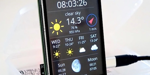
- Displaying the Weather Forecast, so that you know which clothes to pick after the shower
- Do simple settings by using the load cell as input device


Klasse Beitrag, freue mich auf den zweiten Teil! Werde das auf jeden Fall nachbauen! Danke
Hallo Waldemar! Danke für die Blumen! Freue mich immer über Fotos und Erfahrungsberichte von (erfolgreichem) Nachbau!!!
Cheers, Dani
Just curious, could you use the an interrupt to wake it all up? so if you step on the scale it causes the interrupt to fire and wake up?
Hi CrankyCoder. Yes, you could, but I didn’t really see an easy way to accomplish this. Interrupts work with pins switching their states from high to low or the other way around. The load cells which are the only things able to measure someone stepped on the the scale are analog. So the HX711 would have to constantly measure the weight which would be bad for batteries. On the other hand I could add a button which would close as soon as someone steps on the scale, but I found this too complicated. So I ended up the shift switch…
I’m curious though how this could be resolved in a battery efficient way. I know that the off-the-shelve scales can do it…
Hi,
I follow your blog for some time.thanks for sharing with us all of your projects, I find them interesting, specially this body scale one.
When will you publish the second part of this tutorial?
Best regards
Hi André. Thank you for your feedback and the interest in my blog. I hope to soon find time about the second part. I do the projects in the time that is left after work and my family. So please be patient. But soon need to improve the scale, my wife is not really happy with it;-). Then I will also find time to write a blog post about it.
Hi,
I implemented it just the same as you. but, it is not initialized to 0, and it is wrong when weighing with other objects.
What should I do?
please answer about my question.
Hi Jiwoong. Did you follow the part “Smoke Test and Calibration” in this post? After that your scale should be calibrated…
….
scale.set_scale(-500161/1.18);
….
Thank you for your reply.
I measured the weight of a 1.18kg weight, and then added a scale value. If I measure the same thing after calibration, I get 1.18kg. But when I measure different things, the values are different.
please answer about my question.
wdt reset 문제로 곤혹을 치르고 있습니다.
위 코드를 컴파일 하면 자꾸 리셋이 되는데요.
방법좀 부탁드립니다.
….
ets Jan 8 2013,rst cause:4, boot mode:(1,6)
wdt reset
load 0x4010f000, len 1384, room 16
tail 8
chksum 0x2d
csum 0x2d
v09f0c112
~ld
Sorry. The problem is resolved.
thanks
hi boongs
how did you resolve it?
thanks
Having the same problem. How did you solve it please
Mine also reset WDT anyone got this resolved?
the correct diagram to connect the 4 load sensors is in the next link:
http://www.instructables.com/file/FUO46W0I0C96FJG/
I encountered the same issue and solved it by replacing the yield() calls within the HX711.cpp files with delay(1). In some cases those problems also indicate that the ESP is not getting enough power.
It seems your wiring of the load cells is incorrect, or incorrectly labeled in the diagram. (S+ and P+ should be switched)
Damn.. After one hour I just figured it out also (S- and P- are switched)..
This is correct diagram:
https://cdn.instructables.com/FUO/46W0/I0C96FJG/FUO46W0I0C96FJG.LARGE.jpg
And this image is also crucial for reverse engineering (my wires were messed up – black is white, green is black etc.):
https://cdn.sparkfun.com/assets/learn_tutorials/3/8/3/20100816-3wirestraingauge.png
Fantastic work, Daniel! How about the part 2? Is it still on your to-do list? 🙂 Would love to see all those functions listed at the end of part 1. Best regards, Yi
I just built this and it looks and works well. I epoxied a RJ11 jack on the load sensor deck, and again on the box with the ESP, HX711, OLED, etc. This lets me use a standard phone cord and mount the display at whatever height I want.
Then I’ve got a few tweaks:
– I think I’ll add a tar button. I assume I can just activate a “scale.tare();” command using an interrupt.
– I plan on adding buttons for each family member that will send their weight to ThingSpeak – this ought to help lose a little weight. Using your code examples in the weather station kit, I think I can do this.
– Maybe I’ll add a DHT11 – I have a few of these collecting dust.
– I wouldn’t mind having the display show the info from your weather station, when not being used for the scale.
– Maybe eventually I’ll add a body mass index calculator or measurement tool using either height and weight, or electrical resistance.
Any idea, though, how I could make the font larger? I checked the OLEDDisplayFonts.h file and it only goes up to 24pt. It would be nice for the weight to take up the entire height. I’m looking at u8g2 / u8x8, but it looks somewhat confusing. Any ideas?
Thanks for all of your hard work, great ideas, and thorough explanations.
I just built this and at first it worked great. After I messed around with it for a while (modifying the case, hot-gluing components down, etc.), it’s been acting strangely. First, I saw wildly divergent values. Now, with nothing on the scale and scale.set_scale(), the numbers start out at a few hundred and steadily climb, shortly reaching the hundreds thousands before I pull the plug. I’ve tried another Wemos board, tried another HX711 board, measured the resistance between the white-red-black wires (white-880Ω-red-880Ω-black) on each of the four load cells, checked the continuity between the load cell red wires and corresponding pins on the HX711.
Any idea what might be going on? I’ve got a bunch of mods planned, but need to get this ironed first.
Hello,
any news about the scale ? can you publish code for new version of scale that i see on that page with thingspeak and weather support 🙂 ?