

After many hours of work I’m very happy to finally publish all the sources for the ESP8266 PlaneSpotter project. It is not yet really in a V1.0.0 state but I’m sure with the help of the community it will quickly get better. While this post is more a “making-of” you can find build instructions on Github: https://github.com/squix78/esp8266-plane-spotter-color
The Beginnings
A few months back I had already built and published a PlaneSpotter project for the tiny OLED screens. It was quite useful but could only display text information about the nearest plane. How much cooler would it be to have a tiny and affordable device displaying a map with airplanes on it, just like the apps you have on your smart phone? The idea kept coming back to me but one important puzzle piece was missing: the TFT library could only display raw bitmap files (BMP) and I didn’t know of any mapping service which would let you download bmp images. Of course, I could have built a web service which would have converted JPEGs and PNGs to BMPs on the fly but that wasn’t really my goal. So I was stuck with the idea until I recently found Frederic Plante’s fork of the JPEGDecoder library with adaptations for the ESP8266. This suddenly changed the game and I started working on the PlaneSpotter Color project.
The JPEGDecoder library
It seems that this library has seen several iterations and forks. It is built around Rich Geldreich’s picojpeg library which is very good on embedded devices with limited memory. The library was wrapped by Makoto Kurauchi 3 years ago for Arduino. Then Bodmer created a new repository and added more samples until Frédéric Plante ported it to the ESP8266. There might have been too much forking and copying but it is still a very good example for how open source works. Since this library is currently not available in the Arduino IDE library manager you’ll have to clone Frédéric’s repository or download the zip file.

While the maps from MapQuest were displayed without issues I had problems with other JPEG files. The splash screen which I had ordered from a Fiverr designer didn’t display properly on the TFT. I had opened it in GIMP and exported it with the proper dimensions but on the TFT it would always show up with artefacts. I first suspected compression but the artefacts did even shop up with 0% compression (or 100% quality). Another open source tool had to help: ImageMagick’s identify showed me that images which worked at a sampling factor of 1×1, 1×1, 1×1 while my Gimp export had 2×2, 1×1, 1×1. So keep in mind if you want to display your own files.
From what I could tell the library currently cannot decode data from PROGMEM. What does that mean? When you mark a variable or array with the PROGMEM keyword it will not be loaded into your memory after startup but stay packed in your firmware. With a special read command you can then read this data and do what you need with it. Usually font files also use this little trick. This is quite cool since you don’t have to upload images to the ESP8266 by using an additional Arduino IDE plugin. In the WeatherStation Color I had worked around this problem by downloading the moon phase images from my web server. But having the images in the source code is much better. You can create your own images on a Linux/Unix system like this:
xxd -i image.jpg | sed "1s/.*/const uint8_t image[] PROGMEM = {/" | sed "s/ [a-zA-Z_]*_len/ image_len/" > image.h
Explanation: the xxd command creates a hex dump of image.jpg but it doesn’t contain the PROGMEM keyword. So the first sed command replaces the first line with a new one. The second sed replaces the name of the variable that holds the length of the array. Then the file is written to a header file.
I mentioned that the library is currently not capable of loading data from PROGMEM. I therefore wrote a little routine which copies the PROGMEM data onto the SPIFFS file system of the ESP. From there the JPEGDecoder library can read it.
The Wifi GeoLocator
I’m most probably not the first one to do this but I still think it’s worth mentioning. Did you know that your ESP8266 has a GPS device built-in? Well, it is not exactly a GPS device but under certain situations can be even more precise. It works by scanning visible access points and sending them with the signal strength to a web service. If your database is good enough and contains the necessary SSIDs you will get a pretty decent location fix. This only works if you are connected to the internet and if you can call the webservice but hey, it basically comes for free.
Alexandar Mylnikov is running such a webservice which is fairly easy to use:
https://api.mylnikov.org/geolocation/wifi?v=1.1&data=open&bssid=00:0C:42:1F:65:E9
which returns a JSON object:
{"result":200, "data":{"lat": 45.21981301815, "range": 125.417, "lon": 16.54716187303, "time": 1483362238}}
There is also a beta version which takes a base64 encoded list of multiple bssids and the rssi (signal strength) which in theory should result in even higher precision.
Drawing on the TFT
The current setup shows an ugly flickering with the update of the data every few seconds. Sadly I couldn’t find a way around that issue yet and this is for a good reason. In the OLED display library I could just build a frame buffer, do all drawing operations there and then write the whole buffer to the display. But 128*64*1 bits don’t consume so much memory like 320*240*16 . (2 bytes per pixel with a resolution of 320×240). There are certainly some tricks you can use to work around this issue but they would currently consume time I don’t have. If you have suggestions or even pull-requests on github, please let me know.
You might also notice that the flight tracks are not working 100% properly yet. Sometimes they seem to forget their past and start over again.
PCB design, Fritzing and KiCad
In this project I tried out a lot of new things. One of them was designing my own printed circuit board. The board is actually quite simple and only needs to connect the 14 pins of the Touch screen/ TFT with the Wemos D1 Mini. I had used Fritzing to create a wiring diagram so it was easy to turn it into a PCB. After a bit of renaming files I was able to send the Gerbers to http://dirtypcbs.com/ and after about 10 days I had my first ever self-designed PCB in my hands. I soldered the TFT and the Wemos D1 Mini onto the board and everything fit nicely. How big was my disappointment when nothing would light up? I first was afraid that had designed a short between two pins which Fritzing hadn’t warned me about but the connectivity test revealed that I simply had forgotten one connection between the ESP8266 and the display. That could be solved quickly by adding a bodge wire as you can see on the photo:

Even before I had received the Fritzing PCB from dirtypcbs.com I had worked through a great KiCad video tutorial by Chris Garmel (Contextual Electronic). With the help of the tutorial I had a PCB design ready in no time. But I have to say that KiCad is not the most intuitive tool;-). I sent them off to https://oshpark.com/ and received 3 wonderful boards. Sadly I had made a mistake again. The Wemos pins were so far inside of the PCB that I only could attach the USB connector if the Wemos board was soldered with a gap to the connector board. This defied the goal to have a design as flat as possible:

I updated the KiCad file and I’m currently waiting for a new delivery.
OpenScad and the 3D printed enclosure
The last piece of the puzzle was to design an enclosure for the hardware. I like to use OpenScad for that since it lets you “program” the objects which is a good thing for a programmer;-).


Hi,
have you tried TARGET 3001! for PCB Design? Was fairly intuitive for me, maybe helps you as well 😉
Not able to open the enclosed.scad in openscad, see error here :- http://imgur.com/lbcK08J
Any suggestions?
Hi Anthony
How did you get that file? This looks like a website. Please copy paste the content of this link into the openscad editor:
https://raw.githubusercontent.com/squix78/esp8266-plane-spotter-color/master/openscad/enclosure.scad
Let me know if that worked…
Hi, that worked….
I got the file from here : https://github.com/squix78/esp8266-plane-spotter-color/tree/master/openscad
In github when you are looking at the content of a file there is button labelled “Raw”. The link behind that button will show you the real file. Telling from your screenshot I would say you accidentally saved the github page, not the file… Happy that it works now:-). Depending on your setup you might have to make modifications to the openscad file…
And many thanks for your donation, very much appreciated!
I can see only one scad file only the Lid , where is the case bottom ?
Hello, i have the same problem.
Any help???
I’m a little late to show up here, but maybe this will help someone.
To get the other part of the case you just have to go to the last two lines of the file. Uncomment the “allCase();” line and comment out the “lid();” line.
I copy and paste and just get the back cover…any advise
The JPEGDecoder library here:
https://github.com/Bodmer/JPEGDecoder
now supports the ESP8266. The library will plot jpegs from arrays stored in Flash or from the SPIFFS filing system. It should also handle SD card files but this has not been tested on the ESP8266.
Decode and array like this:
JpegDec.decodeArray(plane, plane_len);
Various bug fixes have been made to correct image corruptions and ESP8266 exception generation. I can see image corruption in the picture in this blog in the last MCU (spurious green pixel) and this is due to a bug in the version of the JPEGDecoder library you are using. Unfortunately Frederic’s Plantes branch (which is broken), was branched off quite a while ago and quite a few bug fixes have been added since.
Note that Jpeg rendering times can be halved if raw SPI.writePattern() is used instead of pushColor(). In this case use the byte swap option in the User_Setup.h file to avoid psycodelic images. The map can then be drawn in ~195ms instead of ~420ms which reduces display flicker quite a bit:
// Use this method with SWAP_BYTES defined in User_Config.h (inside JPEGDecoder library)
uint32_t count = mcu_pixels * 2;
uint8_t *pImg8;
pImg8 = (uint8_t*)pImg;
while ( count >=64 ) {SPI.writePattern(pImg8, 64, 1); pImg8 += 64; count -= 64; }
if (count) SPI.writePattern(pImg8, count, 1);
To avoid confllct with the SD library definition of “File” in SPIFFS call up the FS.h file with globals disabled and use fs::File namespace references:
#define FS_NO_GLOBALS
#include
…
fs::File jpgFile = SPIFFS.open( filename, “r”);
Alternatively disable support for the SD library in the User_Setup.h file in the library folder to avoid the compiler error.
File names can now be in the String type.
Note: SPIFFS file names should have a leading “/”, but this has not been added to the downloaded map file name. If the SD library is also loaded the leading / is used by the library to spot SPIFFS file names.
Forgot to mention, if you use the raw SPIwrite approach you need to drop the chip select line after the setWindow() function call and raise it again at the end of the render function.
I can branch the master PlaneSpotter repository at some point and build in all these suggested changes in if this is considered desirable.
Thank you a lot! That makes everything a lot easier. I always prefer to use a “less forked” library. Can you please add library.json and library.properties files to your repository? This allows them to be available through the library manager in the arduino IDE and the platform io lib manager.
See this documentations:
http://docs.platformio.org/en/latest/librarymanager/config.html
https://github.com/arduino/Arduino/wiki/Arduino-IDE-1.5:-Library-specification
And here two examples:
https://github.com/squix78/esp8266-oled-ssd1306/blob/master/library.json
https://github.com/squix78/esp8266-oled-ssd1306/blob/master/library.properties
OK, I have added the .json and .properties files. the .properties file seems to be recognised by the IDE but I do not know how to test/verify the .json file.
I have made other changes, in particular to the rendering function in the example sketches so that arbitrary image sizes can be accommodated. (It used to only handle images of x & y size that were integer multiple of the MCU size.) So now the splash screen image gets correctly rendered.
Hi,
I have tried to use your new library with the plane spotter, and it does not load the map image. I think I have to make some modifications to the code of the plane spotter sketch. But My programming skills are not that good. Can you make a branch version with the changes needed?
I can see the loading of the plane’s is smoother, they are being plotted without the map.
Keep up the good work. 🙂
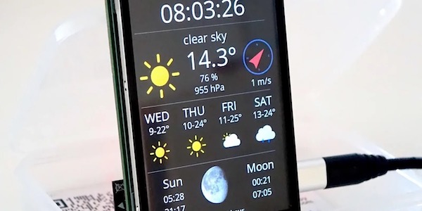
Hello. I collected a weather station by your code. Why do not I see icons? Only the forecast is displayed, but without pictures.
Awesome question?
It’s caused by changes in Adafruit’s GFX library. Here’s the discussion about it, and the solution: https://github.com/squix78/esp8266-weather-station-color/issues/10
How can I change date display up to german?
Weather display I have in Settings const String
WUNDERGRROUND_LANGUAGE = “DL”;
Const String WUNDERGROUND_COUNTRY = “DE”;
Const String WUNDERGROUND_CITY = “Baunatal”;
Weather display as mentioned is in German only time display above is still in English
Is it possible to somehow increase the brightness of the display screen in your kit? I want to use this outdoors on my patio but the screen just isn’t viewable if the sun is out.
Hi all,ordered the kit,now i want to print the enclorsure so lung,but i only get the back cover is Openscad..Any advise would be appreciated..Thank you
I finally made Plane Spotter Color working, after some wrestling with jpeg decoder libraries. You are a coding genious! It is a great application and it works great. Thanks so much for sharing it.
I got the plane tracker working for the Carpinteria California area. Very Cool! Is there a way to change the units of measure from metric to imperial? I’m looking at the sketch and haven’t found a way to do that yet.
Greetings Dani!
This project: ‘ESP8266 PlaneSpotter Color’ fits better with a larger screen, such as 4″ to 7″ (inches); because of its useful area. Thanks
So I ordered the Color LCD Kit from Amazon and I figured while i wait a couple of days for delivery, I’d print the enclosure and be ready for the board when it arrived. I received the board today and lo and behold, I see the board and layout have changed and the assembly no longer fits the enclosure! Are there any plans to update the openscad files to reflect the new layout? Thanks Dan
Hi – I jus purchased and built the kit from Thingpulse, and got it put together. When I powered it up, it displays the splashscreen, but it just sits there saying Connecting to wifi. Is there somewhere that I have to set my SSID and password that I am missing?
Are you trying to run the plane spotter? This uses the WiFi Manager, you have to connect to the device from your computer or smartphone by finding the SSID accesspoint. Then you can set your own WiFi credentials…
Yes, I am. OK, now that makes sense, forgive me, missed seeing that anywhere. I have tried to reload it (loaded successfully once), but now it keeps giving me Error compiling for board errors.
OK. I FINALLY got it to compile and upload. I uninstalled Arduino IDE in Windows, then went into File Explorer and deleted every single reference to it, then Regedit and did the same (I went nuclear!) I then reinstalled the IDE, then the boards and then the libraries and it compiled and uploaded successfully. It starts, then says connecting to Wifi, then the little plane draws a line across the bottom and goes away, and that’s where it sits, only showing the splash screen… DId I miss something?
Sorry to bother sir. I got the Plane Spotter to compile and upload. The splash screen comes up, it says connecting to wifi… for a few seconds, and then that goes away, the “plane progress bar” goes across the bottom then goes away, and then nothing but the splash screen. I pulled up the wifi on my phone looking for it, but I don’t see anything that looks like it. Help?
I’ve even gone in and uncommented the reset setting line, connected to the plane spotter, entered my wifi credentials and saved them. As soon as I do, it’s wifi AP goes a2ay, it connects to my wifi, the progress bar displays and we’re reight back stuck at the splash screen.
And in the splash screen, when I touch it, it goes away and then displays a screen with a blue dot in the center, and the lines that say pan, com+, com-, rack. ?
Hi Doug. I just sent you an email. Please use our support forum at https://support.thingpulse.com/ for your questions. We can better help you there…
It appears the Adsb Exchange is no longer available for free. Therefor the Plane spotter color app no longer works. Is this a correct assumption? Has anyone encountered this issue. I’ve seen no comments since 2020.